Difference between revisions of "HackerHotel2019Badge/Soldering"
Jump to navigation
Jump to search
| Line 22: | Line 22: | ||
[[File:IMG 2700.jpeg|400px]] | [[File:IMG 2700.jpeg|400px]] | ||
| − | Grove connector goes on the board like this. Since the two pads for physical strength are not connected, please add some superglue for extra strength. | + | Grove connector goes on the board like this. Since the two pads for physical strength are not connected (sorry...), please add some superglue for extra strength. |
Latest revision as of 04:20, 10 February 2019
Parts[edit]
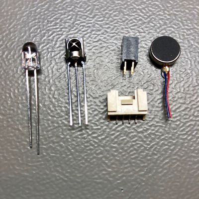
In the kit are from left to right: IR LED, IR Receiver, Shitty Addon Connector, Grove Connector, Motor
Well, we lied. the IR Receiver might not be in your kit. Please pick one up in the Badge Hacking Area.
IR LED and Receiver[edit]
[[1]]
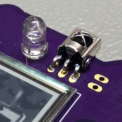
IR LED should be on the front side. The IR LED is a polarized component so align the short leg of the LED with the flat side of the silkscreen drawing.
The IR Receiver should be assembled as above.
Shitty Addon Connector[edit]
It's a square 4pin header. You'll figure it out ;) it needs to go on the front(display)side of the board, and you solder on the backside.
Grove connector[edit]
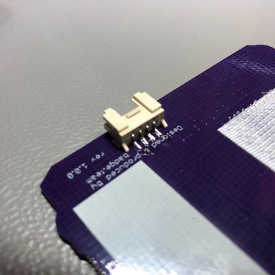
Grove connector goes on the board like this. Since the two pads for physical strength are not connected (sorry...), please add some superglue for extra strength.


